Friday, December 24, 2021

M1 PRO vs 12600k


It has come to this. Apple releases a supped up version of their mobile chip with tons of ad-hoc silicone and now mops the floor with intel.

How bad is it?

4K H265 scrubbing in Resolve

M1 PRO 16 GB + 512 GB SSD 

20% utilization, scrubbing is as smooth as h264 or braw

12600K + 2060RTX 32 GB + god-knows-how-many TB of SSD

sluggish, the on-chip gpu (quicksync) is maxed out, in term of usability this falls into the forgetaboutit category.


Reimporting the plugins folder of a large project in Unity

M1 PRO 16 GB + 512 GB SSD 

26 seconds of editor freeze

12600K + 2060RTX 32 GB + god-knows-how-many TB of SSD

60 seconds lol


Conclusion: if you want to game dev or edit, buy a mac.

Friday, March 5, 2021

Caddx Nebula Pro & DJI FPV Goggles v2


23ms

WOW!
Seeing that low latency after being on the fence feels good, what felt even better was how tight the controls felt.
See, I just ditched my ev200 as it kept rebooting in mid flight and, when I decided to buy into HD as it's the same price as a decent pair of analogs, I was expecting higher latency.
Instead I got merging. This is a whole new world.
The Armattan Gecko and my shoddy default 4.1 PIDs suddenly felt like a pro rig.

How are the goggles? You've all seen reviews about the v2, nothing else to say so I'll focus on the one time caveats. 
  • The ms readout when your caddx is powered but the FC is not armed will read some crazy high number like 60ms, don't panic, it's how they lower power consumption and prevent burning the chip, that's what someone at DJI told me and that's true. As soon as you arm the FC the latency drops to the insanely low 23ms.
  • There is a menu item that says "SWITCH TO FPV". If you press it then, after rebooting, your goggles are in a mode that only links to the new DJI drone and can't link to the vista anymore. If that happens, again don't panic and just go into settings>switch to ... whatever it's called, then power off then power on and you're back to the mode you want.
  • If you don't see the OSD turn on custom OSD somewhere in the settings menu.

Now onto the caddx, you've seen how good the full sun footage look. Instead of optimum condition I flew it at sunrise under low light condition and it wasn't stellar, in fact it looked like analog, except that branches could be seen and there was zero static at distance. That thing is technically quite remarkable and more importantly the dogs love it.
One thing I quickly did is shield the video cable with fiberglass tape to protect from small branches. It also improves the forward aerodynamics of the the Gecko.

Sunday, September 27, 2020

OfferUp + Google Pay = 100% scam

If you purchase something for shipping on offerup and the seller wants to transact outside of Offerup, do it via "Paypal - Purchase Good" because it protects your transaction in the very high likelihood that you don't receive it.

In typical Google fashion, Google Pay has ZERO customer protection. In fact, in a recent case, they turned down a request for refund stating that "we make it very clear than you should only use Google Pay when you know the other party personally".

So Offerup + Google Pay = 100% scam.

Wednesday, May 20, 2020

Building a TELESCOPIC permanent pier

based on these posts: https://www.cloudynights.com/topic/685801-manzanita-hill-observatory-is-under-way/   https://www.cloudynights.com/topic/704770-project-cinder-block-pier/

summary: the pier itself can be made out of metal anchored on a concrete slab, concrete tube or cinder blocks.
The mount plate is then anchored in the pier.
The mount is bolted to the mount plate.

The mount plate
The mount plate can be done by re-purposing a brake rotor as seen here $10
The base of the fork mount is about 9" in diameter and has 2 sets of 3 holes. The innermost set is about 3" from center, the set we're interested in is the outtermost which are 80mm from the center.
The screws ar3/8" x 16 tpi (ref. @mclewis1)


2020-06-20: Upgrading to a telescoping pier. Based on Davey-T design.

Outer tube: square tube 6", I'll angle grind the brake to fit inside the 6" tube then tap 4 holes at 3/8" x 16tpi
Inner tube: 4 x iron angles welded together. Could be replaced by a 5" square tube if the linear actuator can fit and not be a pain to weld in place. Here is an idea: weld the linear actuator to a base then weld the base inside the 5", problem is how do I remove it when the LA fails? idea: weld the lower angle that the LA is attached to to a tapped piece of metal then bolt that piece of metal to the 5"

In-between: 5mm PTFE sheets
Motor: Linear actuator
Details: Two bolts to tighten things up after movement.
FCAW Welder: 
Back from the metal scrapyard with scrap, now training the welding.
I can still smell the flux hours later, that can't be good. Flushed water through my nostril made it go away. The next day wore masks and now I no longer smell metal in my nose.

For the inner tube Davey uses 4 iron angles. This is a good alternative to the central tube because it reduces the space between inner and outer tube and also makes mounting and replacing the linear actuator easier as there is space to nudge it. A shorter 5" central tube is cut in half and iron angles are welded to it - or bolted from the inside, the iron angles need to be tapped. Space is reduced from over 8mm to 2mm which is easier to find PTFE for.

Tuesday, March 31, 2020

Fixing the Nexstar 11 GPS rollover

Nexstar built after 2002 suffer from GPS 1024 week rollover, the fix is to upgrade the hand controller with a firmware that offsets the date.
The problem I have with that is no more GPS align, makes the telescope look like a robot, which is cool.
So let's try to replace this wonky GPS with something home brewed, based on this cloudynights thread.

The idea is to replicate the serial board of the Celestron with a cheap microcontroller that will convert the GPS data into Celestron serial code and transmit them in TTL.

Since I was dabbling or blabbing in electronic 2 years ago I have a few parts that I can use. A nodeMCU mini and a Beitian BN-180.

The BN-180 works at 9600 bauds by default.


Connecting the proper pin requires to translate D pin name into GPIO, GPIO is what arduino understands.


Testing it with the full example in the tinyGPSPlus library with proper pin results in this
even after 30 minutes so it's likely that the BN-180 super capacitor discharged and it's rebuilding an entire satellite almanac, which on this one takes a long time, also it's indoors, and GPS don't like forests. Let's wait and if it doesn't work then we'll get a better GPS. After a while it gives a lock but with few satellites.

Switched over to a Arduino Nano because the Nano can take up to 12V in and output 3.3 or 5V, oh and the digital signal is 5V compatible with the Nexstar.

It works better with the BN220 and gets a lock for 7 sats indoor, but then loses it when I use the computer, I think the proximity to 3 large LCD screens scrambles the reception.

It would be nice to use the quality japan made patch antenna of the celestron, it seems to use a MHF3 ipex connector which doesn't fit the UFL of the new GPS module. I left a note on eevblog forum :) I know aliexpress has that stuff but i don't want to wait 2 weeks.

This NEP-7N gets 5 fixes within seconds but then drops when the antenna is moved.

Onto the wiring.
Get Rj12 from ebay
Use the desinsulators to expose a few wires
 
tin with this cheapo excellent active head soldering iron, it's fast!

Beowulf made it work https://github.com/LordBeowulf/nexstar_gps
Here is the correspondence between the rj12 and the internal cable.

Tuesday, February 18, 2020

PST Mod Stage 0.5 for Dummies - How to make a Solar Telescope without breaking the bank or burning your eyeballs

So, like me you got the PST but it's not enough and you know .001 zilch about optics?

The following is a condensate of SolarChatForum that is dumbed down enough to make a PST mod easy.
I had my sights on a mod 2, meaning replacing the back with a good focuser and the front with more powerful optic but I don't understand enough about optic so I want to start safe and cheap. This more humble blog is about a mod 0.5: replacing the back with a good focuser that doesn't wobble around, something with enough back focus (focus plane range) that you can use any binoviewers.

First you disassemble your PST.

to do that you unscrew the golden tube

and with this thing

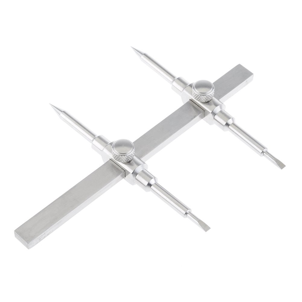
you unscrew the corrector lens in front of the etalon

tada now the etalon is ready to be unscrewed


push hard


This is your etalon. Étalon is a French word which means standard of measurement, and also stallion.

If you're in a mood to disassemble everything you can unscrew the eyepiece holder, it won't be used but why not. (EDIT: this part is essential)

the tiny one at the bottom of the eyepiece holder is purple, maybe a UV filter?
Then we get the one that's attached to the black box, it's glued in so it'll take a bit more work.


ITF stands for Induced Transmission Filter and it's a bandpass for H-alpha 656nm. Acording to this site, this tiny element costs $75!
I don't know why there is another H-a bandpass after the etalon.

These shiny lenses protect your eyeballs from blindness, give them a hug.
Now onto the last bit which is glued.

Notice the blue golden color of the prism, I think it's treated to filter the beam. Since we're not using it, are we risking our eyesight?
Heat it up the glue with a heatgun

wrap the bit with paper

clamp and twist


put the ITF+UV assembly back together,it will go to the end of the back.


then fit this SCT nosepiece to the back of the etalon

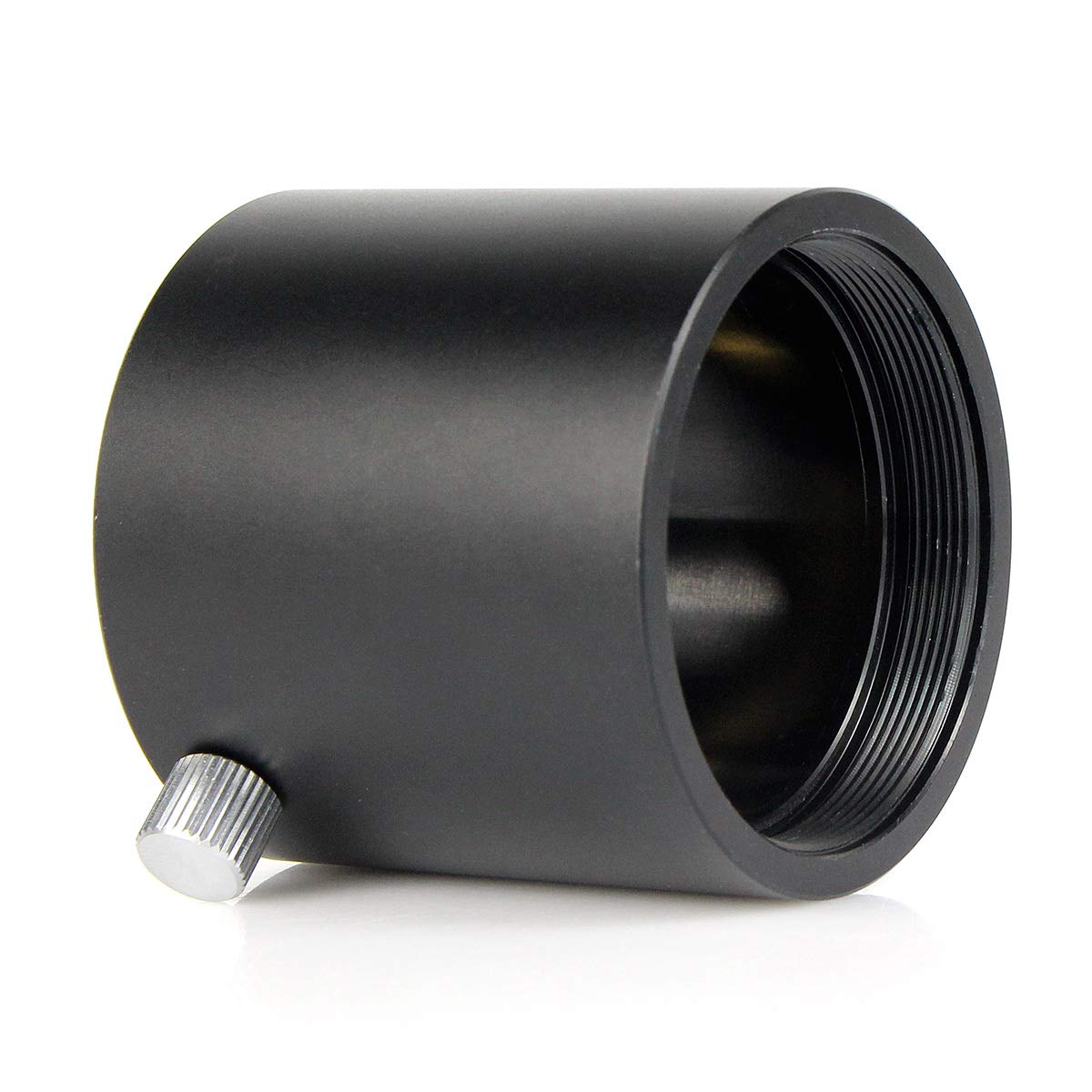
the M48x.75 female fits perfectly

Then add a few other bits to recreate the 200mm back, here I'm experimenting with 1.25mm 2x barlow then a 1.25mm helical focuser.


Now why do we have to put 200mm of back behind the etalon?
The PST is a telescope with a focal length of 400mm. Focal length means distance behind the lense where the beams converges into a focused image. It's commonly represented as lines intersecting (blue in the diagram). The etalon is 200mm behind the front, it counts as 0mm towards the beam travel to the focal plane so there is 200mm more to go.
Why does it count as 0mm? The Fabry-Perot etalon needs beams that are parallel to do its precise boucy light thing but the front lense converges the rays into a cone. To correct that, the etalon is flanked by two plano lenses (yellow in the diagram). The plano concave at the front turns convergent beams into parallel beams to feed the etalon and the plano convex lens behind the etalon turns the now-filtered parallel beams back into convergent beam.


what's missing now is the adapter to fit the end of the helical focuser M42 male to the ITF assembly's M32 male.

The simplest solution was found by Marty in SolarChatForum, it is to unscrew the eyepiece holder of a diagonal and replace it with the stock ITF assembly.
And here is the result.


If there is sun tomorrow I shall test it.

The sun was up, I placed a binoviewer in the focuser and put my eyes in it.
I could feel something tingly inside the eyeball so I stopped and re assembled the PST stock, looked again, no tingly.
The brightness was the same so my guess is that the pentaprism inside the black box of the stock PST reduces infrared by a lot.

Needless to say I took the discussions about filtering IR and UV VERY VERY seriously.
After much reading people who have been doing this or know the science, I came to a temporary conclusion that the ideal mix of filter is a.
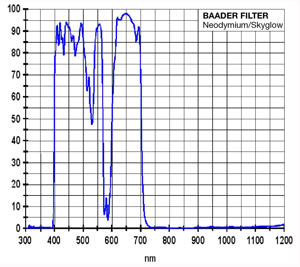
Baader moon and skyglow or a 35nm CCD h-alpha filter to reject IR and UV around the visual spectrum
BelOptik KG3 to reflect IR beyond 1200nm, it is good in the far IR like a KG3 and
Here are the graphs, you can see they are complementary in the far IR and it is coated to reflect IR thus preventing filter from cracking under heat expansion. Here is a demonstration

Alternate to a Beloptik is a cheap KG3 and a reflective near IR but I'm sure the price will be the same.
Since these filters are glass only, I must find a way to hold them in a 2" tube.


EPILOGUE
I returned the PST, got a Quark and an Orion 120mm and it was EPIC!

Saturday, November 23, 2019

How do you do Oculus Rift roomscale the easy way?

Bypass the USB-A low power delivery of your motherboard and use a USB-C hub like THIS ONE

This tiny box muxes 4 x USB3.0 signals into a USB-C signal which in the case of this z370 motherboard leads to collision free communication and also pushes usb-C higher power to all 4 usb-A ports.
The result is tracking and audio with no glitch.

Mansplaining (maybe): Each sensor eats up 76 MB/s and in USB 2.0 mode 16 MB/s, goggle audio probably eats up 48 kHz@16bits X 2 = much less than 1 MB/s total with 2 sensors: <160 180="" 3="" and="" mb="" p="" s="" sensors="" with="">Why does this collide on the z370 internal USB controller but not via a usb-C hub? My guess is power supply of the hub via usb-c increased power delivery makes the end point's electronic more stable so the signal timing is more stable, less for the z370 controller to correct, no loss tracking.
It might be why a powered USB-A will also provide stable tracking. In other word it's not the bandwidth as much as enough power to the sensors.